Springs for Trailer Ramps, Lids, Hatches & Gates

Definition: Torsional torsion springs designed and manufactured to be installed into gates,trailer ramps, doors, hatches, and lids to complete a leverage function by making it easier to lift or lower the gate, ramp, lid, or door.
The springs used for trailer ramps, doors, hatches, gates and lids are torsion springs. These springs are made up of round wire helically wound to make coils. The ends of torsional springs are known as legs for the wire on the end coils sticks out as if it were a lever. The the torsion spring legs are what allow for your gate, ramp, door, hatch, or lid to apply a rotational force on the spring making it deflect within a range of 360.

There are a few formulas an guidelines to follow before purchasing torsion springs for your gate, ramp, door, hatch, or lid. You must know the weight and length of the ramp or lid to calculate the amount of spring force you need as well as the diameter of the shaft going through the spring’s inner diameter to hold it in place, the width of the ramp or lid to know how much room you have for several torsional springs to work in parallel and be able to support the weight of the gate or ramp, the free angular positionfree angular position of the spring which is determined by the amount of coils, the direction of wind which determines the direction your spring will deflect, and the working torques including pre-loadpre-load to be sure that your torsional springs will meet such requirements.
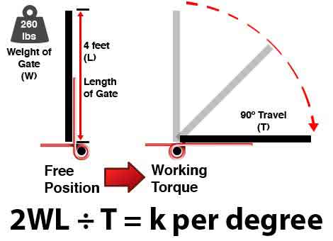
To calculate the amount of torsion spring rate per degree you need, multiply the length of the rampby the weight of the ramp by two and divide the product by the degrees your spring must travel including pre-load as shown in the example and diagrams below.
Examples
You have a gate that weighs 260 pounds (lbs) with a length of 4 feet (ft) that needs to travel a total of 90 degrees (º).
2WL ÷ T = k per degree
2 (weight * length) ÷ travel = rate of inch-lbs/per degree
2(260x 4) ÷ 90 = k of inch-lbs/per degree
2(1,040) / 90 = k of inch-lbs/ per degree
2,080 / 90 = k of inch-lbs/ per degree
23.1111 = k of inch-lbs/ per degree
Formula Diagram

Now that you know how much force you will need, you may divide the rate/per degree by how many springs you need to work in parallel in order to meet your required torque values. You may also do the opposite in case you don’t have a spring yet but already know how many springs you plan to install.


 English