Rotational Springs
Definition - Also known as torsion and torsional springs. Wire springs whose coils twist to perform a rotational motion. When torqued and released, they store and eject energy.
Rotational springs are both stock and custom items here at China Spring Products Corp. We have hundreds of rotational springs in stock just waiting to be bought off the shelf. Before deciding whether you would like to purchase stock or custom rotational springs, you must have an accurate, functional torsional spring design.
The first dimension you must determine on a rotational spring design is direction of wind. The direction of wind will determine which one of your spring’s legs will rotate clockwise or counter-clockwise, the front or the back leg. One of the legs will most likely be stationary, which is why the direction of wind is important.
Most of our stock rotational springs have both left hand and right hand versions of each other. You may also come across some designs that are only made in one direction of wind. Let`s say you need a right hand spring but you only find a left hand spring with the dimensions you require. In this case, you will need to have a custom rotational spring manufactured to meet your requirements.

Another important factor when it comes to torsional springs is free position. Keep in mind that you will most likely want to have your rotational springs pre-torqued. In order to achieve this, you will need your spring’s free position to have less degrees than your pre-torqued spring. This can actually give you a better chance of finding a similar spring in stock with a free position that will work in your device. All you need is for it to be positioned a few degrees less.
For example:
You need your spring to be installed under a 90º pre-torqued position. Anything between 45º and 85º should do the job as shown in the pre-torque diagram to the right. Just make sure you don’t exceed the torsional spring’s elastic limit under the working torques.

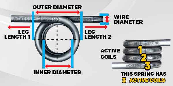
The next step to designing your spring is measuring the spaces within and around it. If your spring is going over a shaft (most likely it is), you must measure the diameter of that shaft and be vigilant of your torsional spring’s inner diameter. A rotational spring’s inner diameter will contract and become smaller as it is being torqued. Make sure that the torqued inner diameter is not smaller than the shaft where you’ll be installing the spring. When it comes to outer diameter, you verify that it will fit within the space available for the spring’s installation.
Wire diameter and total coils will determine the body length of your torsion spring as shown in the diagram to the right. To calculate the body length, you must multiply the wire diameter by the total coils and add the wire diameter once again. You are basically counting the total active coils but without skipping a wire.

The previous measurements will set the tolerances around your spring’s physical dimensions. The physical dimensions assure that your spring fits into your application or mechanism. The force and elasticity determine that the spring will actually work under your device’s required torques.
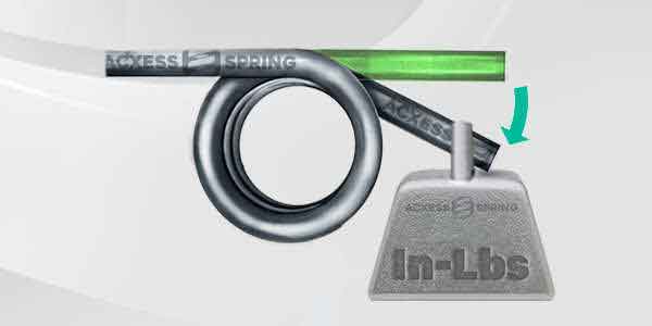
Torsion spring rate per degree is the amount of torque required to make your spring’s legs travel one degree as shown in the diagram to the right. This means that for every degree of travel, the torque will constantly increase the same amount of inch-pounds.
For example:
You have a torsion spring that needs to travel 45 degrees with a torque of 9 inch-pounds. In order to calculate the required spring rate per degree divide the torque by the degrees of travel. For this spring, the required spring rate would be 0.2 inch-pounds (in-lbs).
To double check your work, multiply the rate by the distance traveled. You’ll see that 0.2 multiplied by the distance traveled of 45 degrees gives you a total torque of 9 inch-pounds.


 Español